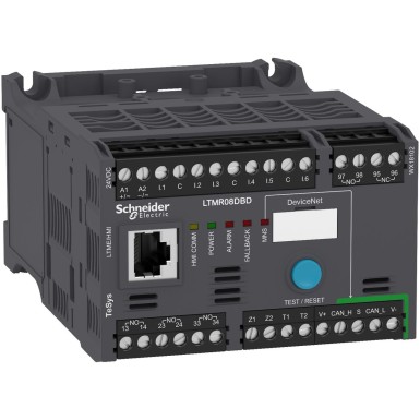
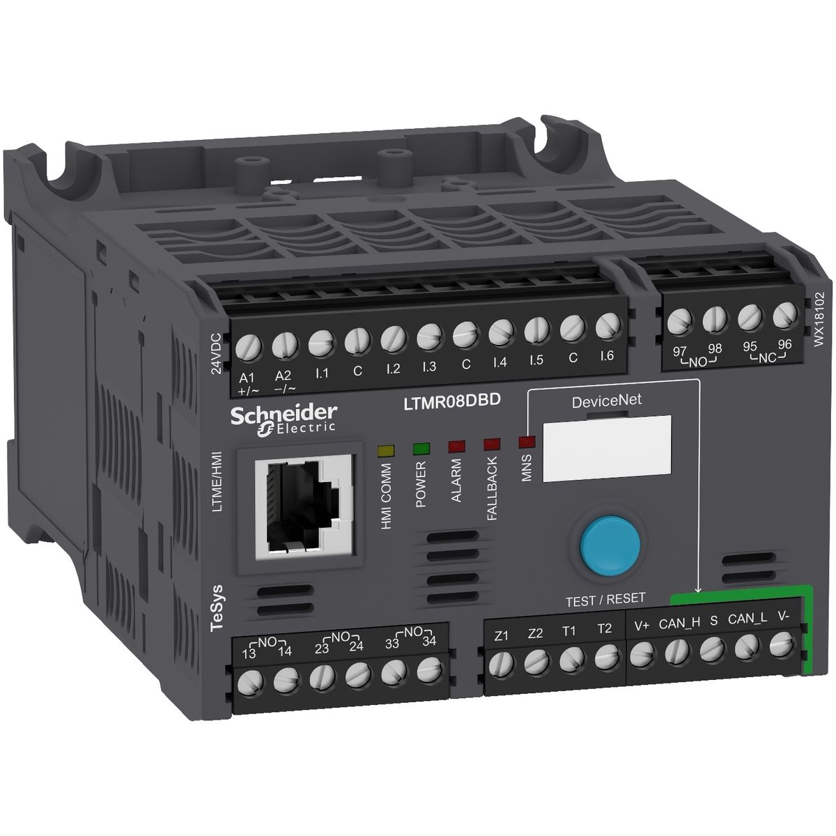
LTMR08DBD - Motor controller, TeSys T, Motor Management, DeviceNet, 6 logic inputs, 3 relay logic outputs, 0.4 to 8A, 24VDC - Schneider Electric
690 V conforming to CSA C22.2 No 14
690 V conforming to UL 508
DNV
GL
UL
C-Tick
BV
CSA
ATEX
RINA
KERI
CCC
ABS
EAC
RMRoS
NOM
0.8 kV communication circuit conforming to EN/IEC 60947-4-1
0.8 kV supply, inputs and outputs conforming to EN/IEC 60947-4-1
Control circuit: connector 1 cable(s) 0.2…2.5 mm² (AWG 24...AWG 14) flexible without cable end
Control circuit: connector 1 cable(s) 0.25…2.5 mm² (AWG 24...AWG 14) flexible without cable end
Control circuit: connector 1 cable(s) 0.2…2.5 mm² (AWG 24...AWG 14) solid without cable end
Control circuit: connector 2 cable(s) 0.2…1 mm² (AWG 24...AWG 14) flexible with cable end
Control circuit: connector 2 cable(s) 0.2…1.5 mm² (AWG 24...AWG 14) flexible without cable end
Control circuit: connector 2 cable(s) 0.5…1.5 mm² (AWG 24...AWG 14) flexible without cable end
Control circuit: connector 2 cable(s) 0.2…1 mm² (AWG 24...AWG 14) solid without cable end
0.5 A gG for control circuit
3 NO
5 A at 30 V DC for logic output
Vibrations plate mounted: 4 Gn, 5...300 Hz conforming to EN/IEC 60068-2-6
Shocks half sine wave acceleration: 15 Gn for 11 ms conforming to EN/IEC 60068-2-27
1 % voltage (100...830 V)
3 % power factor
5 % earth fault current external measurement
+/- 30 min/year internal clock
0,02 temperature
1 % current
5 % active and reactive power
Temperature
Earth-fault current
Average current Iavg
Imbalance current
Waiting time after overload tripping
Remaining operating time before overload tripping
Phase fault and earth fault trip counters
Starting current and time
Trip history information
Trip context information
Motor control command recording
Running hours counter/operating time
Event recording
30 W (DC-13), Ie = 1.25 A, 500000 cycles (output)
Overload
Power factor variation
Reverse polarity protection
Earth-leakage protection
Thermal protection
Overload (long time)
Phase failure
Load fluctuation
Phase unbalance
Locked rotor
Radiated RF fields, 3, 10 V/m, conforming to EN/IEC 61000-4-3
Fast transients immunity test (other circuits), level 3, 2 kV, conforming to EN/IEC 61000-4-4
Fast transients immunity test (on supply and relay outputs), level 4, 4 kV, conforming to EN/IEC 61000-4-4
Voltage dips and interruptions immunity test, 70 %, 500 ms, conforming to EN/IEC 61000-4-11
Conducted RF disturbances, 10 V, conforming to EN/IEC 61000-4-6
Temperature sensor: surges (serial mode), 0.5 kV, conforming to EN/IEC 61000-4-5
Temperature sensor: surges (common mode), 1 kV, conforming to EN/IEC 61000-4-5
Control circuit: surges (serial mode), 1 kV, conforming to EN/IEC 61000-4-5
Control circuit: surges (common mode), 1 kV, conforming to EN/IEC 61000-4-5
Communication: surges (common mode), 2 kV, conforming to EN/IEC 61000-4-5
Relay outputs and supply: surges (serial mode), 2 kV, conforming to EN/IEC 61000-4-5
Relay outputs and supply: surges (common mode), 4 kV, conforming to EN/IEC 61000-4-5
CSA C22.2 No 14
UL 508
IACS E10
IEC 60947-4-1
960 °C conforming to UL 94
48 h conforming to EN/IEC 60070-2-11
TH conforming to EN/IEC 60068
LTMR08DBD is a industrial TeSyS LT solution designed for professionals. BaltElec specializes in wholesale and product distribution in Estonia, Latvia, Lithuania, and Finland.
- Original Schneider Electric product, certificates and compliance documents available.
- Volume-based pricing – request a quote for larger quantities (MOQ may apply).
- Fast delivery across the Baltics and Finland; cooperation with trusted couriers.
- Technical support and selection assistance based on your requirements.
Pricing: Request a project quote. The price depends on quantity, delivery, and payment terms.
TeSyS LT specifications may vary by model. For an exact match, please send us your requirements or check the technical data sheet.
FAQ for LTMR08DBD - Schneider Electric
-
Does your company provide bulk pricing for
LTMR08DBD?
Yes, project discounts are available. Send us a list of required quantities (e.g. Schneider Electric, LTMR08DBD, 5 pcs) and we’ll prepare a project-specific quotation.
-
What is the availability and delivery time for LTMR08DBD in the Baltics
and Finland?
We provide fast turnaround for deliveries to Estonia, Latvia, Lithuania, and Finland. Exact lead time depends on quantity and batch availability, confirmed upon quotation.
-
Is LTMR08DBD by Schneider Electric an original product?
Yes. We only sell Schneider Electric authentic products with manufacturer’s warranty. Compliance certificates are available on request.
-
Is LTMR08DBD suitable for my TeSyS LT project?
We help confirm compatibility efficiently. Please provide conditions (voltage, current, environment, standards), and we’ll compare them to Schneider Electric technical requirements.
-
How does delivery and invoicing work?
We deliver via logistics partner to Estonia, Latvia, Lithuania, and Finland. Invoicing is done according to quotation; bulk purchases are priced individually.
