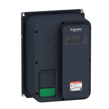
ATV320U07M2W - Variable speed drive, Altivar Machine ATV320, 0.75 kW, 200...240 V, 1 phase, enclosed - Schneider Electric
Relay output R1A, R1B, R1C on resistive load, cos phi = 1: 3 A at 30 V DC
Relay output R1A, R1B, R1C, R2A, R2C on inductive load, cos phi = 0.4 and L/R = 7 ms: 2 A at 250 V AC
Relay output R1A, R1B, R1C, R2A, R2C on inductive load, cos phi = 0.4 and L/R = 7 ms: 2 A at 30 V DC
Relay output R2A, R2C on resistive load, cos phi = 1: 5 A at 250 V AC
Relay output R2A, R2C on resistive load, cos phi = 1: 5 A at 30 V DC
ATEX
NOM
GOST
EAC
RCM
KC
ATEX
UL
CSA
EAC
RCM
AI2 bipolar differential voltage: +/- 10 V DC, impedance: 30 kOhm, resolution 10 bits
AI3 current: 0...20 mA (or 4-20 mA, x-20 mA, 20-x mA or other patterns by configuration), impedance: 250 Ohm, resolution 10 bits
Flux vector control without sensor, standard
Voltage/frequency ratio - Energy Saving, quadratic U/f
Flux vector control without sensor - Energy Saving
Voltage/frequency ratio, 2 points
Negative logic (sink)
Software-configurable voltage AQ1: 0...10 V DC impedance 470 Ohm, resolution 10 bits
DI1...DI6 logic inputs, 24 V DC (30 V)
DI5 programmable as pulse input: 0…30 kHz, 24 V DC (30 V)
4...16 kHz with derating factor
Adjustable 0...300 %
Not available in voltage/frequency ratio (2 or 5 points)
Open collector DQ- 0…1 kHz 30 V DC 100 mA
CANopen
8.4 A at 240 V (heavy duty)
U
S
CUS
Ramp switching
Acceleration/deceleration ramp adaptation
Acceleration/deceleration automatic stop with DC injection
Overcurrent between output phases and earth: drive
Overheating protection: drive
Short-circuit between motor phases: drive
Thermal protection: drive
Communication module, EtherCAT
Communication module, Profibus DP V1
Communication module, PROFINET
Communication module, Ethernet Powerlink
Communication module, EtherNet/IP
Communication module, DeviceNet
Configurable relay logic R1B 1 NC electrical durability 100000 cycles
Configurable relay logic R1C
Configurable relay logic R2A 1 NO electrical durability 100000 cycles
Configurable relay logic R2C
Class 3S2 according to IEC 60721-3-3
40…60 °C with derating factor
Radiated radio-frequency electromagnetic field immunity test level 3 conforming to IEC 61000-4-3
Electrical fast transient/burst immunity test level 4 conforming to IEC 61000-4-4
1.2/50 µs - 8/20 µs surge immunity test level 3 conforming to IEC 61000-4-5
Conducted radio-frequency immunity test level 3 conforming to IEC 61000-4-6
Voltage dips and interruptions immunity test conforming to IEC 61000-4-11
ATV320U07M2W is a industrial Altivar 320 product designed for companies. BaltElec specializes in wholesale and product distribution in Estonia, Latvia, Lithuania, and Finland.
- Authentic Schneider Electric product, certificates and compliance documents available.
- Project pricing – request a quote for larger quantities (MOQ may apply).
- Efficient logistics across the Baltics and Finland; cooperation with logistics partners.
- Technical support and application suitability advice based on your requirements.
Pricing: Request a project quote. The price depends on quantity, delivery, and payment terms.
Altivar 320 specifications may vary by model. For an exact match, please send us your application details or check the technical data sheet.
FAQ for ATV320U07M2W - Schneider Electric
-
Does your company provide wholesale prices for
ATV320U07M2W?
Yes, project discounts are available. Send us a list of required quantities (e.g. ATV320U07M2W, Schneider Electric, 10 pcs) and we’ll prepare a project-specific quotation.
-
What is the availability and delivery time for ATV320U07M2W in the Baltics
and Finland?
We provide reliable logistics for deliveries to Estonia, Latvia, Lithuania, and Finland. Exact lead time depends on quantity and batch availability, confirmed upon quotation.
-
Is ATV320U07M2W by Schneider Electric an original product?
Yes. We only sell Schneider Electric authentic products with manufacturer’s warranty. Compliance certificates are available on request.
-
Is ATV320U07M2W suitable for my Altivar 320 application?
We help confirm compatibility efficiently. Please provide conditions (voltage, current, environment, standards), and we’ll compare them to Schneider Electric technical requirements.
-
How does delivery and invoicing work?
We deliver via logistics partner to Estonia, Latvia, Lithuania, and Finland. Invoicing is done according to agreement; bulk purchases are priced individually.

